
TIVA Microcontroller Circuit
TIVA TM4C123G LaunchPad Evaluation Kit is used as the main microcontroller of this project. Four shift registers are cascaded together to provide all logic-level signals to sub-circuits. 7 PWM outputs, 6 signal inputs, and one extra signal line for the solenoid are directly wired from the TIVA board.
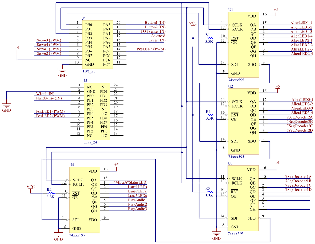
7 Segment Display Circuit
Two 7 segment display modules are used to display the game score. In order to save pinouts, a 7 segment decoder (7447 BCD) is added to each display module. In such way, the 14 signal lines are reduced to 8. The signal lines are wired to the pinouts of the shift registers.

Input / Sensor Circuits
Coin Detection Sub-circuit - Detects the insertion of TOT. A coin sensor is used, which is essentially a pair of IR emitter and receiver. The non-linear IR signal conditioning configuration with a schmitt trigger is sufficient for TIVA digital input pinout to recognize the signal.

Button and Lever Switch Sub-circuit - Detects whether the player presses WATER or FIRE button, or pull the "MEGA-BLAST" lever. The input pins stay HIGH by enabling the internal pull-up resistors in TIVA. Whenever the button or level switch is triggered, the corresponding pin goes LOW.

Wheel Sub-circuit - The player turns the wheel to select among three lines of corns. A potentiometer is wired as a voltage divider to allow TIVA to read analog input signal.

Palm Detection Sub-circuit - Detects whether the player has his hand cover the palm box. A photoresistor is used in a voltage divider configuration. Resistance of the photoresistor increases with decreasing incident light intensity, which causes the change in voltage. And this voltage is taken as the analog input signal to the TIVA.

LED Circuits
|
Lane Selection LEDs - Three red jumbo LEDs are used to indicate how close is the wheel aiming direction to each of the individual lanes. The PWM output signal is wired to the gate of 2N7000 to allow the fast ON and OFF switching of the transistor, which achieves the objective of changing the brightness of the LED. Resistor values are carefully selected such that the transistors are operated in the saturation range (1 : 10 current ratio).
|
|

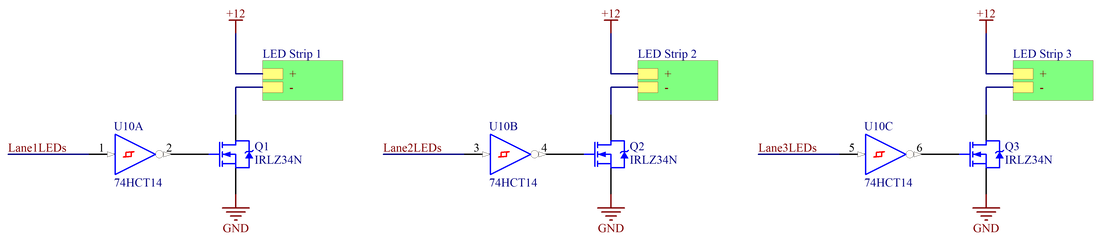
LED Lane Stripes - The 12V cool white LED strip at the lane turns on if the wheel aims towards that specific lane. Hex inverters are used to boost 3.3V signal HI from TIVA to 5V, so that the MOSFETs can be turned on. The LED strips has internal resistors built-in, therefore an additional current-limiting resistor is not necessary on the Drain side.
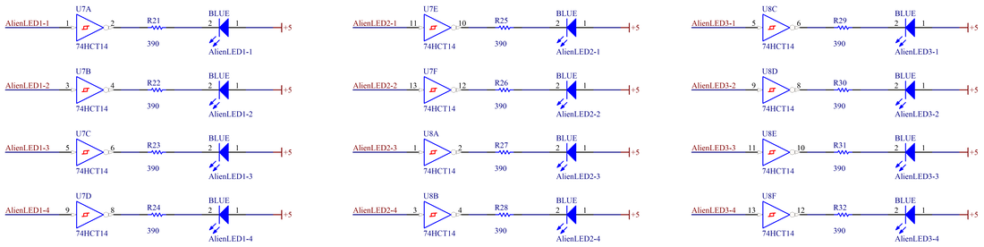
Alien LEDs - Three groups of four blue LEDs are representing the descending aliens that pose a threat to the corns. Hex inverters are used to boost 3.3V signal HI from TIVA to 5V.
"MEGA-BLAST" Status LEDs - The two yellow jumbo LEDs indicates whether the "MEGA-BLAST" feature is ready to be activated. Circuit design is exactly the same as the alien LEDs.

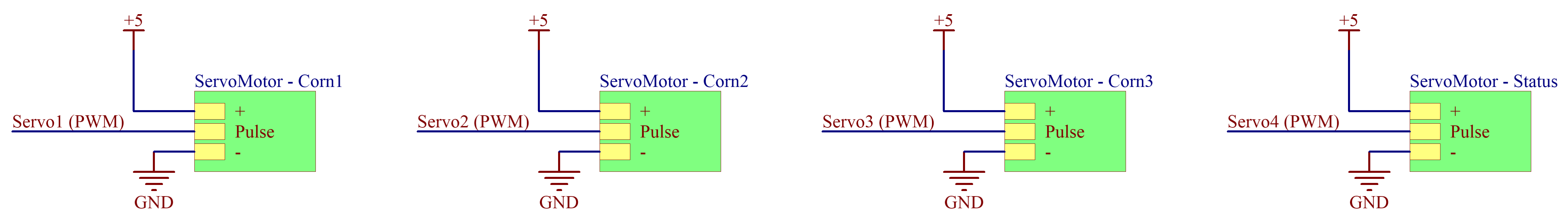
Servo Motor Circuits
Servo motors are controlled by sending PWM signals through the control wire. By changing the pulse width of the signal, position of the servo arm can be controlled precisely. Three micro servos are used as the inputs to the rack-and-pinion mechanisms. The fourth micro servo is directly attached to the status clock.
TOT Return Circuit
TOT hold and return are achieved by the ON and OFF of a solenoid. Control signal is wired to the gate of a MOSFET. Moreover, a diode is placed in parallel with the solenoid as a protection, because solenoid is essentially an inductor which generates large voltage spike during discharging time.

Sound Board Circuit
A sound board is used in the project to provide audio feedback through a headphone to players. A pre-loaded audio clips will be played when the certain signal line is pulled low. The output pinouts of the sound board are wired to a 3.5mm headphone jack.

Bypass Capacitors
Bypass caps (decoupling caps) are used to remove any AC noise that may be presented on a DC signal, producing a much cleaner and pure DC signal.

